Introduction

The goal of the project is to mimic a copier jam, as if two detectors next to each other is jammed, then an alarm will go off. The inputs is the detectors and the button that turns off the alarm. The outputs is the alarm and LED lights.
Beginning
How did you create a truth table?
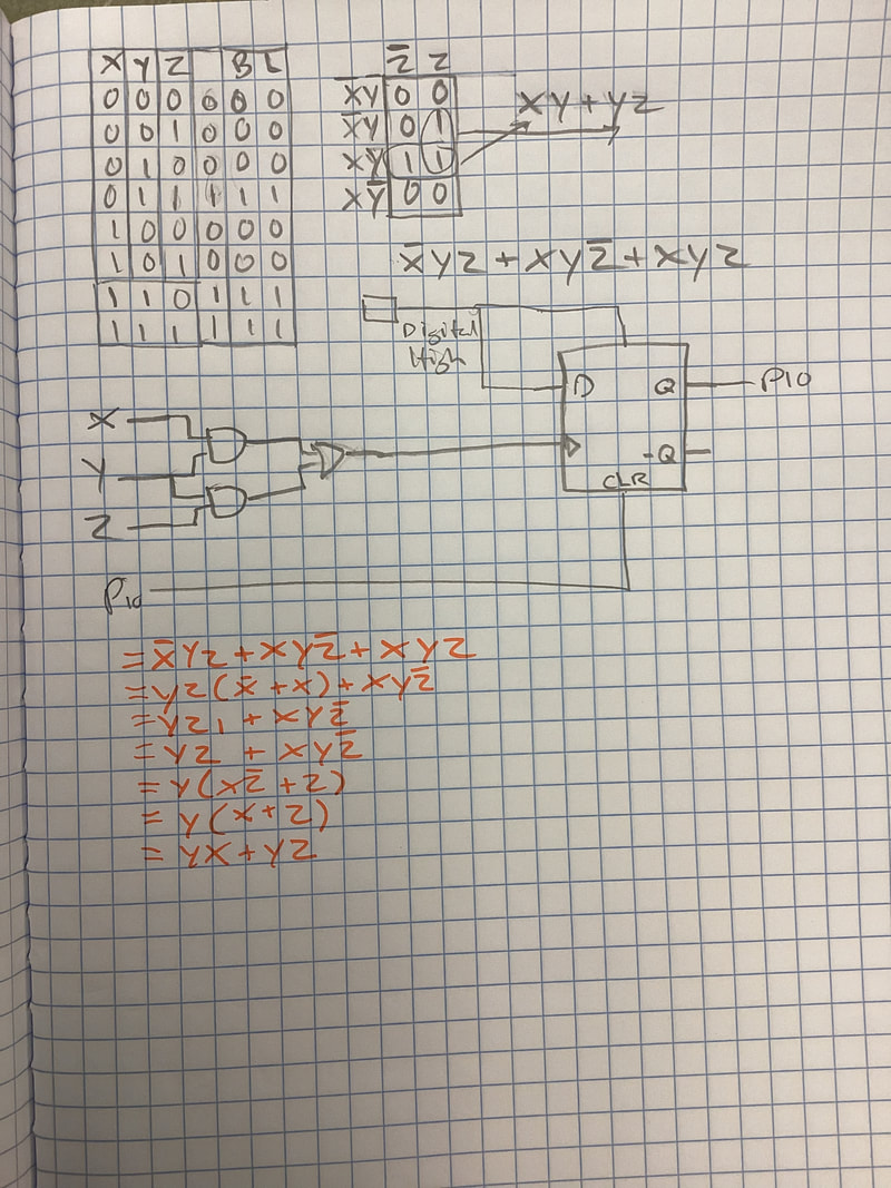
I created a truth table that would represent if a copier jam happened, it would show B and L when it is on or off depending on the binary count of X, Y, and Z.
Input/Output:
X, Y, and Z represented the three copier jam detectors as an input. LED and Buzzer will be the outputs that will be on if X and Y or Y and Z are on.
We used Consensus Theorem, Distributive Law, and Boolean Algebra; X + 'X = 1.
K-mapping helped simplify the expressions and had the same results as Boolean Algebra. The unsimplified expressions represents the copier jam when X and Y or Y and Z are both turned on.
Circuits
It was not that it was complicated, it was more so a bit confusing since there were multiple factors to keep in mind of since we had to keep troubleshooting. We used resistors to reduce the current for the circuit. The purpose of combinational logic circuit is that it is more efficient and can be used for implementation due to it using a lot of logic to maintain the circuit. The flip flops are used because there is stored data that can be changed by applying varying inputs, as well as flip flops have the ability to store data unlike other circuits. The LED goes off and on when there is something detected but the motor stays on due to when it is triggered and stays on due to the memory component that the flip flop has.
wiring
I simplified the expression and used a flip flop that used logic for the input, and the logic was just turning the expression into gates. I built it in Multisim before I started wiring. It used an integrated circuit and needed simple wiring to the right place to be able to make it work. The reason flip flop makes this circuit possible due to the memory component that the flip flop has compared to other circuits since other circuits cannot keep the memory of a previous action. Hence why the alarm stays on even after you turn the detectors back on, which would not be the case for any other circuits.
conclusion
We essentially created a circuit on Multisim and tested it, when the circuit works we then configured it to the integrated circuit and wired the breadboard to the copier jam detectors, along with the buzzer and LEDs. I learned how to configure on integrated breadboards, how to utilize the buzzer and LEDs, and I learned how to use copier jam detectors and connect it to a circuit. Thus I learned how to actually use the breadboard. Overall, I feel much more comfortable with Multisim, maybe a bit weak in the technical aspects of utilizing short cuts. My comfort level with wiring is much better than before, I feel perhaps I could definitely practice some more since I feel a bit insecure about my abilities to wire well.
